Раздел: Документация
0 1 2 3 4 Step 3 Install the Power Box
Drill 4 holes on desired locations  Tighten4screwstofix thepower box (These four screws are not supplied. User must prepare their own screws.)
Drill holes on the intended positions of of the wall. (Goose Neck) Step 4 Connection • Outdoor Housing Connection DC12V Input RS-485 Alarm In AlarmOutput DXdDg O g о zz n Г)Г\Г\Г\п fVYWYVV ooooooo ooooooo Fan&Heater FastDome ACOutput ACInput Wiring Wiring -> VideoOutput 1. Connect AC / DC cables: 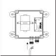  Untighten the left Connect the AC knob, put the AC power cable to AC power cable through Input jack the hole and tighten the knob ConnecttheAC Connectthe DC powercable(below) powercable(above) toAC Outputjack to DC Inputjack 2. Connect Alarm, telemetry control (RS-485) and Video cables: 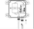 Untighten the right knob, put the Alarm, RS-485 and video cables through the hole and tighten the knob 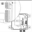 Connect the telemetrycontrol (RS-485) to RS-485 Input (TXDI+,TXDI-) 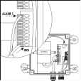 Connect the Alarm input cable to Alarm Input (Alarm1&GND) 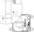 Connect the video cable to output jack Outdoor Housing for IP Series Connection RS-485 AlarmIn AlarmOutput DXdDg O g DC12V Input Fan&Heater, Wiring 30000 3000000000
FastDomeWiring 1. Connect AC / DC cables: ACOutput ACInput RJ-45 VideoOutput  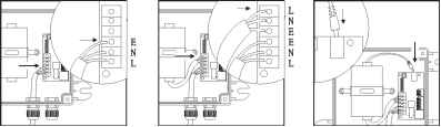 Untighten the left Connect the AC knob, put the AC power cable to AC power cable through Input jack the hole and tighten the knob ConnecttheAC Connectthe DC powercable(below) powercable(above) toAC Outputjack to DC Inputjack 2. Connect Alarm, RS-485, RJ-45 and Video cables:
Untighten the right knob, put the Alarm, RS-485, RJ-45 and video cables through the hole and tighten the knob  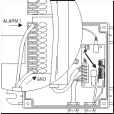 Connect the telemetry control (RS-485) to RS-485 Input (TXDI+,TXDI-) Connect the Alarm input cable to Alarm Input (Alarm 1 & GND) 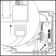 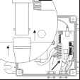 Connect the network cable to RJ-45 jack Connect the video cable to output jack Step 5 Attach the Base to Housing 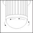 Turn the dome cover anti-clockwise  Turn the camera body anti-clockwise "[щишшцц  Separate the dome cover from camera 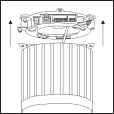 Separate the camera bodyandbase  Untighten the 3 screws from base 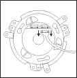 Unplug the connection cable 0 1 2 3 4
|
||||||||||||||||||||||||||||||||||||