Раздел: Документация
0 ... 3 4 5 6 7 8 9 ... 19 Pendant Mounting (External Housing) Step 1 Separate PSU and Bracket 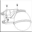 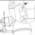 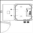 • Untighten the screws fromPSUbox • Untighten and pull out the bolt from the hinge • Separate the housing andPSUbox Step 2 Install Power Supply Unit 1.1 When use 24Vac power source:  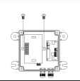 • Putthe PSUinto the box • Tighten2screwsto fix the PSU 1.2 When use 90 ~ 260Vac power source: 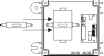 ? f • Put PSU into the box • Put the clamp on PSU Step 3 Install the Power Box • Drill 4 holes on desired locations
• Tighten2screwsto fix the PSU • Tighten4screwstofix the powerbox. (These four screws are not supplied. Usermust prepare their own screws.) Step 4 Connection RS-485 Alarm In AlarmOutput 5pOqZ Ozzz DC12V Input ooooooo ooooooo I I Fan&Heater Fast Done Wiring Wiring 4.1 Connect AC/DC cables: AC Output AC Input 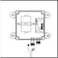 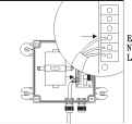 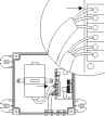 -► Video Output 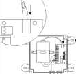 • Untighten the left • Connect the AC knob, put the AC power cable to AC power cable through Input jack the hole and tighten the knob • Connectthe AC • Connectthe DC powercable(below) powercable(above) to AC Output jack to DC Input jack 4.2 Connect Alarm, telemetry control (RS-485) and Video cables:  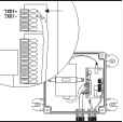 • Untighten the right knob, put the Alarm, RS-485 andvideo cables through the hole and tighten the knob • Connect the telemetry control (RS-485) to RS-485 Input (TXDI+,TXDI-) 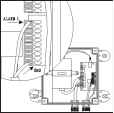 • Connect the Alarm input cable to Alarm Input (Alarm1&GND) 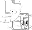 • Connect the video cable to output jack Step 5 Attach the base to housing 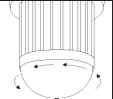 • Turn the dome cover anti-clockwise  • Turn the camera body anti-clockwise 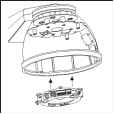 • Attach the base to housing Step 6 Camera Setting 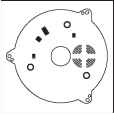 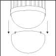 • Separate the dome cover from camera 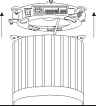 • Separate the camera body and base 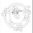 • Connect the housing cable 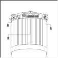 • Untighten the 3 screws from base  • Unplug the connection cable 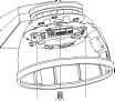 ft i • Tighten 3 screws to fix base Setting Fast Dome ID Setting Alarm Mode Setting Camera Function (17X & 22X optical lens models only) Setting Fan Power Refer to page 8,9 for the setting 0 ... 3 4 5 6 7 8 9 ... 19
|
||||||||||||||||||||||||||||||||||||||||||